IIR Filter
Filtering is the operation which removes or changes specific frequency components from the signal. In SIGVIEW, you can simply apply a filter to the signal by defining the frequency segment to be removed, or the segment you want to leave in the signal. That way, you can create band-stop, band-pass, high-pass, and low-pass filters.
SIGVIEW includes two types of filters:
•FFT filter: Signal is converted in the frequency domain by using FFT function. Filtering is applied in the frequency domain and the signal is then transformed again into the time domain by using Inverse-FFT function (see this help chapter for further information).
•IIR filter: Filtering is performed by using one of standard Infinite Impulse Response filters. That type of filtering is described in this chapter.
For a more powerful filtering method, see the 3D-filter function.
When you select the “Signal tools/IIR Filter...” option from the main menu, a dialog will appear where you can choose the filter type, enter segment boundaries (in Hz) and determine if you want to remove that frequency segment (band-stop), leave only that frequency segment (band-pass), or if you want to remove all frequencies up to (high-pass) or above some frequency (low-pass).

SIGVIEW supports three standard IIR filter types:
•Bessel: This IIR filter gives a nice domed response in frequency, and also a nice domed response in time. This is something approaching the ideal balance between time-locality and frequency-locality for an IIR filter.
•Butterworth: This IIR filter gives flat responses away from the transition areas and sharp transitions, especially as the order increases. However, this sharp frequency response is paid for with a wider and wider time-response. In other words, it gives sharply defined frequency-locality, but less well-defined time-locality.
•Chebychev: This IIR filter exchanges some of the flatness in the passband of the Butterworth filter for a sharper fall-off at the cut-off frequency. The resulting filter also has a less well-defined time-locality. The amount of permitted passband ripple is specified in dB.
Modifying filter properties
In the filter window, open context menu and choose Properties... option. The above dialog will open again, allowing you to change filter properties. Additional "Apply" button will appear in the lower left part of the dialog, enabling you to apply filter settings directly, without closing the dialog.
The "Reset filter after each processed block" setting controls whether a fresh filter is applied to every new block of signal or if the signal processing continues with the existing state after a block is completed. Deactivate this feature if your signal is continuous, meaning all the blocks being processed are sequential.
What can I do if filter creation was not successful?
For some combinations of filter parameters and input signal, it will not be possible to calculate the filter. In that case, you will see the corresponding message in the filter dialog. In that case, you should try changing the filter parameters, usually from-to frequencies or filter order, until filter can be created successfully.
Generally, you should avoid creating bandstop or bandpass filters with frequencies near the theoretical min/max frequencies of the spectrum. It is much better to create lowpass or highpass filters in that case.
Dealing with transient effect at the beginning of the signal
If you apply filter on the complete input signal, beginning with first sample, you will sometimes see high amplitude at the beginning of the filtered signal. It is a transient affect caused by the fact that the filter needs some signal length until it can deliver valid values:
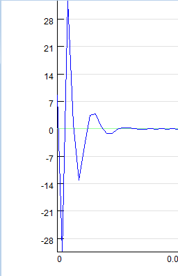
To deal with this, you can simply apply filter only at a part of the input signal. In that case, SIGVIEW will use signal part before the block you are filtering to train the filter and to avoid transient effect in the signal part you are actually filtering.
This option will be used only if "Reset filter after each processed block" option is turned on.