FFT Filter
Filtering is the operation which removes or changes specific frequency components from the signal. In SIGVIEW, you can simply apply a filter to the signal by defining the frequency segment to be removed, or the segment you want to leave in the signal. That way, you can create band-stop, band-pass, high-pass, and low-pass filters.
SIGVIEW includes two types of filters:
•FFT filter: Signal is converted in the frequency domain by using FFT function. Filtering is applied in the frequency domain and the signal is then transformed again into the time domain by using Inverse-FFT function. That type of filtering is described in this chapter.
•IIR filter: Filtering is performed by using one of standard Infinite Impulse Response filters (see this help chapter for further information)
For a more powerful filtering method, see the 3D-filter function.
When you select the “Signal tools/FFT Filter...” option from the main menu or press the ![]() toolbar button, a dialog will appear where you can enter segment boundaries (in Hz) and determine if you want to remove that frequency segment (band-stop), leave only that frequency segment (band-pass), or if you want to remove all frequencies up to (high-pass) or above some frequency (low-pass).
toolbar button, a dialog will appear where you can enter segment boundaries (in Hz) and determine if you want to remove that frequency segment (band-stop), leave only that frequency segment (band-pass), or if you want to remove all frequencies up to (high-pass) or above some frequency (low-pass).
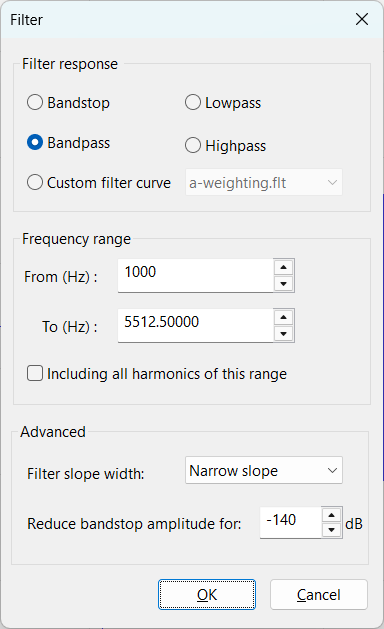
For the band-stop and band-pass filter types, you can also include all higher harmonics of the defined frequency segment. If the defined segment is [x,y], it will also include all segments [N*x, N*y], where N=2..Nmax.
There is also an option to use custom filter curves for signal filtering. For details, please see the Custom filter curves section.
Advanced options
"Filter slope width" selection: If you choose a wider slope, the filter will have a slower transition from band-stop to band-pass frequencies, but it will also have less unwanted frequency artefacts, ripples in spectrum etc.
"Reduce band-stop amplitude for" value: This will determine which amount of energy will be reduced in the band-stop part of the signal. The default value, -140 dB, is equivalent to a full removal of the frequency components.
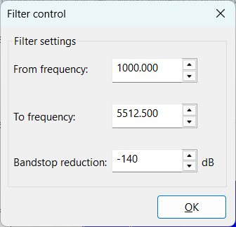
Modifying filter properties
After pressing OK, a new window with filtered signal will appear. You can change the filter’s frequency boundaries or band-stop amplitude later by selecting “Edit/Properties” in the filtered signal window from the menu. You will be able to instantly see how these changes affect the filtered signal.
Background information & filter quality
For this function, SIGVIEW uses an FFT-based filtering algorithm. It is a combination of the FFT calculation, modifications in the FFT result (filling some frequency bands with zeros or applying a custom filter curve), and the inverse FFT calculation. This method is usually faster than other filtering methods, but is also quite accurate.
The filter will deliver much better results if it can access a part of the signal before and after the time segment you are actually filtering. If this is not provided, you will at times observe signal artefacts at the beginning and at the end of the filtered signal.
Therefore, it is recommended not to filter the whole available signal but to zoom-in to a smaller part of the signal and then apply the filter function.