Calibration
Signal input from A/D converters is interpreted by SIGVIEW merely as a series of numerical samples, each bearing distinct values. Take, for instance, audio data from a sound card, which typically spans from -32767 to 32767 due to its 16-bit depth. Such numbers, in isolation, lack any direct physical correlation. To imbue these raw figures with tangible significance - transforming them into units of Voltage, meters, Celsius, etc. - requires instructing SIGVIEW on the process of converting these abstract numbers into concrete physical measurements. This process is encapsulated within a 'calibration file'. Users have the flexibility to generate numerous calibration files to suit different data collection tasks.
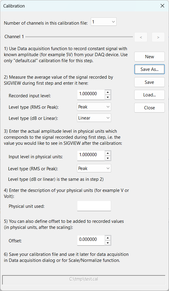
Each calibration file is capable of holding calibration specifics for several channels. The dialog's upper section features a combo-box for selecting the desired channel count. For the purpose of alternating between channels while making edits, the dialog is equipped with '<' and '>' buttons on its right, facilitating easy navigation.
By selecting the “Data acquisition/Sound card calibration” option from the main menu, you can open a calibration dialog where you can create a calibration file in 6 simple steps:
Selecting the "Data acquisition/Sound card calibration" from the main menu launches a calibration dialog, allowing the creation of a calibration file through a straightforward six-step process:
1.Initiate the recording of a steady signal with a known amplitude (e.g., 5V) from your data acquisition (DAQ) device via the "Data acquisition" menu. Utilize the "default.cal" file exclusively for this initial procedure.
2.Determine the average signal level captured by SIGVIEW in the first step and input this figure into the "Recorded input level" field. You can choose if the value you determined was an RMS or Peak value, and if the value was in dB or Linear. This will depend on the way you measure the value. For example, if you use RMS Instrument to measure the amplitude, then you should switch to the 'RMS' type. If you use a spectrum tool with dB units, you should switch to dB type.
3.Input the genuine amplitude of the signal (recorded in step one) in physical units into the "Input level in physical units" box. Here, you can specify whether this measurement should be treated as a peak or RMS (Root Mean Square) value. dB/Linear type will be the same as in step 2.
4.Specify the physical units of measurement (e.g., 'V' for Volts) in the "Physical unit used" section. It will be used only as axis label.
5.If necessary, define any offset (positive or negative) that should be applied to the recorded values, expressed in physical units.
6.Conclude by saving your calibration file, which can then be applied to future data acquisition tasks through the "Data acquisition" dialog.
Alternatively, if your sensor manufacturer already provides sensitivity values which can be used to transform input levels in physical units, you can follow this procedure:
1. For example, sensor documentation states that acceleration sensor delivers 0.025V / 1g. Your DAQ device delivers directly voltage measured by the sensor, and you would like to convert it to g
2. In the "Recorded input level" field, enter the value of 0.025
3. In the "Input level in physical units", enter the value of 1
4. In the field "Physical units used", enter "g"
All calibration files should be saved in the “Calibration” folder located in the SIGVIEW's application data directory (usually C:\Documents and Settings\<UserName>\Application Data\Sigview\). Each of these calibration files can be used later for data acquisition.
There are two special data acquisition files which are included in SIGVIEW setup:
- "default.cal": It leaves recorded data from the DAQ device just as they are, without any conversion. You should not change the content of this file.
- "Automatic calibration": For some driver types which provide functions for automatic conversion from sample values into physical units, this calibration type will perform the calibration automatically and deliver samples values in physical units. This function is currently supported only for "Universal Library" driver type (MCC devices).
Using Calibration function for unit conversion
Calibration function can also be used for a conversion of values delivered from a sensor into a different unit. For example, if your sensor is delivering values in m/s2 , and you would like SIGVIEW to display values in "g" units (Acceleration of gravity), you would create a calibration with the following values:
Recorded input level: 1.0
Input level in physical units: 0.101972
Physical unit used: g
Offset: 0.0